Shape
Copyright David & Cynthia Thomas, 2009
Linear Transformations--Concepts and Connections
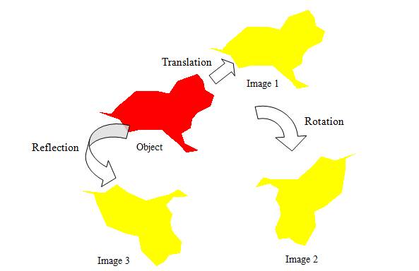
Figure 4.13: Three Isometries
In Figure 4.13, a dog-like object is repositioned on the page using three different transformations. Each of these transformations is also an isometry. The word roots of isometry, iso- and -metry, indicate same-measurements. In other words, every isometry transformation creates an image the same size and shape as the object from which it was made. Corresponding segments in the object and image have equal length, corresponding angles have equal measures, and so on. Elementary mathematics focuses on three isometries: Translation, rotation, and reflection. Each of these transformations repositions the object on the page without changing its dimensions.
· Image 1 in Figure 4.13 was created by translating, or sliding, the object up and to the right an unspecified distance. In Figure 4.14, segments connect corresponding points on the object and its image under translation. Compare the segments? How would you describe their relative lengths? Their relative slopes? Any one of these segments could be thought of as a slide arrow characteristic of the translation. How could you use a slide arrow to specify a transformation?
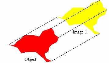
Figure 4.14: Translation
· Image 2 in Figure 4.13 was created by rotating the object through an unspecified turn angle about an unspecified turn center on the page. In Figure 4.15, a segment connects the dog’s nose in the object to the corresponding point in Image 2. A second segment connects the tip of the dog’s tail in the object to the corresponding point in Image 2. A perpendicular bisector is drawn to each of these segments. Their intersection determines the turn center and segments drawn from the turn center to corresponding points on the object and Image 2 determine the turn angle. How could you use a turn center and turn angle to specify a transformation?
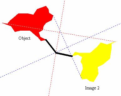
Figure 4.15: Rotation
· Image 3 in Figure 4.13 was created by reflecting the object in an unmarked mirror on the page. In Figure 4.16, a segment connects a pair of corresponding points on the object and Image 3. The perpendicular bisector of this segment is the mirror for the reflection. How could you characterize a reflection using this approach?
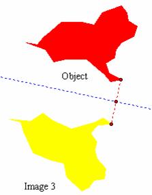
Figure 4.16: Reflection
Every rotation is specified by a turn center and a turn angle. Varying either of these specifications can dramatically change the location and orientation of the image relative to the object. Table 4.5 illustrates four different results obtained using different turn centers and turn angles. Using the Geometers Sketchpad model 4_Rotation.gsp, experiment with the relationship between turn center, turn angle, object, and image. Note that the turn center itself may or may not overlap the object and that the image may or may not overlap the object.
|
|
|
|
|
|
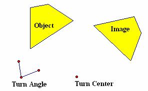
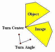
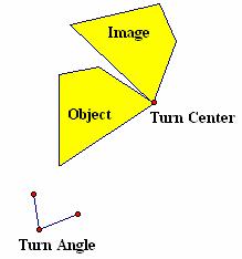
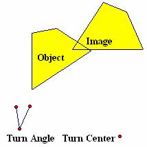
Table 4.5: Rotation Turn Center vs. Turn Angle
Every reflection is specified by a mirror. Varying the position of the mirror relative to the object can dramatically change the location and orientation of the image. Table 4.6 illustrates four different results obtained using different mirrors. Using the Geometers Sketchpad model 4_Reflection.gsp, experiment with the relationship between mirror, object, and image. Note that the mirror itself may or may not overlap the object and that the image may or may not overlap the object.
|
|
|
|
|
|
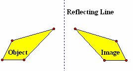
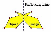
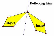
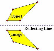
Table 4.6: Reflection Mirror
Performing Transformations by Tracing and Paper Folding
Tracing and paper folding provide a simple model for investigating translations, rotations, and reflections. Figure 4.17 illustrates the use of two sheets of unlined paper to model translation. On the sheet labeled Original, a triangle is drawn in the center of the page. A second sheet labeled Copy is placed on top of the Original so that the edges align. The triangle is then traced. Holding the Original sheet in place, if the Copy sheet is moved up and to the right, the image of the triangle on the Original sheet, as seen through the Copy, appears to move down and to the left. At some point, a second tracing of the triangle is made on the Copy sheet. The two tracings on the Copy sheet are related by a translation.
|
|
|
Figure 4.17: Translation by Tracing
Figure 4.18 illustrates the use of two sheets of unlined paper to model rotation. On the sheet labeled Original, a triangle is drawn in the lower right quadrant of the page. A second sheet labeled Copy is placed on top of the Original so that the edges align. The triangle is then traced. Next a pin is pushed through both sheets of paper into a suitable backing, locking the Turn Center in place on both sheets of paper. Holding the Copy sheet in place, if the Original sheet is rotated counterclockwise, the image of the triangle on the Original sheet, as seen through the Copy, appears to rotate. At some point, a second tracing of the triangle is made on the Copy sheet. The two tracings on the Copy sheet are related by a rotation.
|
|
|
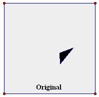
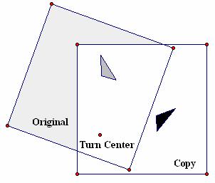
Figure 4.18: Rotation by Tracing
Figure 4.19 illustrates the use of one sheet of unlined paper to model reflection. A triangle is drawn in the lower right quadrant of the page. Next, a fold is made that covers up the triangle. The triangle is then traced on the back of the sheet. When the sheet is unfolded, the triangle traced on the back is traced again on the front of the sheet. The original triangle and the tracing on the front of the sheet are related by a reflection.
|
|
|
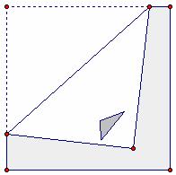
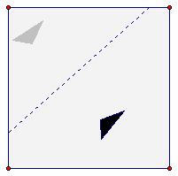
Figure 4.19: Reflection by Folding and Tracing
Performing Transformations by Geometers Sketchpad
The Geometers Sketchpad has a number of features (See Table 4.7) that support transformation geometry. Using these tools, it is a simple matter to select objects for transformation, slide arrows, turn centers, turn angles, mirrors, and dilation, the equivalent of photographic enlargement or reduction. These features make performing geometric transformations and constructing complex geometric patterns accessible to even young learners. By contrast, traditional paper and pencil (i.e., straightedge and compass) techniques for transformation geometry and its applications are too complex and tedious for elementary school students.
|
|
|
|
|
|
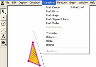
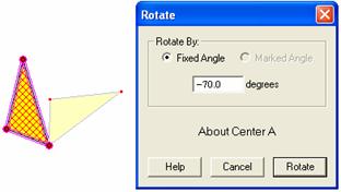
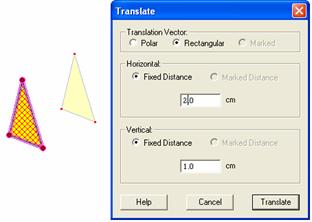
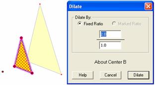
Table 4.7: Geometers Sketchpad Transformation Menu
Composing Transformations
Just as an object may undergo a transformation to
produce an image, so may the image itself be transformed to produce a second
image. Figure 4.20 illustrates this concept using successive
reflections. In the first case, ![]() is
reflected in mirror m, producing image
is
reflected in mirror m, producing image ![]() . A second mirror n is then
drawn parallel to m. The image of
. A second mirror n is then
drawn parallel to m. The image of ![]() in mirror n is
in mirror n is ![]() . Comparing
. Comparing ![]() and
and ![]() , it is apparent that
, it is apparent that ![]() may be viewed as the image of
may be viewed as the image of ![]() under a translation. In
other words, the composition of two reflections may be viewed as a translation
when the reflecting lines are parallel. Using the Geometers Sketchpad
model 4_ComposeT.gsp, find the relationship
between the two distances highlighted in the figure.
under a translation. In
other words, the composition of two reflections may be viewed as a translation
when the reflecting lines are parallel. Using the Geometers Sketchpad
model 4_ComposeT.gsp, find the relationship
between the two distances highlighted in the figure.
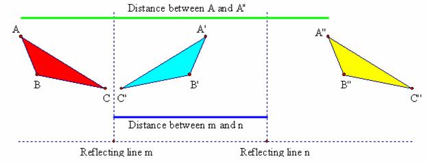
Figure 4.20: Composition of Reflections is Parallel Mirrors
A different result is obtained when the reflecting
lines, m and n, intersect (See Figure 4.21). In this
circumstance, it is apparent that ![]() may be
viewed as the image of
may be
viewed as the image of ![]() under a rotation.
Or, the composition of two reflections may be viewed as a rotation
when the reflecting lines intersect. Because both translations and
rotations may be expressed in terms of reflections, reflections are considered
the most elemental, or fundamental, of the isometries. Using the Geometers
Sketchpad model 4_ComposeR.gsp, find the
relationship between the two angles highlighted in the figure.
under a rotation.
Or, the composition of two reflections may be viewed as a rotation
when the reflecting lines intersect. Because both translations and
rotations may be expressed in terms of reflections, reflections are considered
the most elemental, or fundamental, of the isometries. Using the Geometers
Sketchpad model 4_ComposeR.gsp, find the
relationship between the two angles highlighted in the figure.
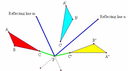
Figure 4.21: Composition of Reflections in Intersecting Lines
Compositions of transformations are not limited to the use of reflections. Beginning with any object, a series of transformation (e.g., first translate, then rotate, then translate, then reflect, and so on) could be applied that creates a succession of images in the plane. If the original object and all successive images are erased as the most recent image is created, the object would appear to move about the plane in leaps. If these transformations occur rapidly enough, the motion would appear to be smooth. This strategy is behind the manipulation of textual graphics seen on television at the start of news and other regularly scheduled programs.
Similarity Transformations
Similarity transformations generate images that are geometrically similar to, but not necessarily congruent to, given objects. A familiar context for similarity transformations is the enlarge/reduce operation available on many photocopying machines. In Figure 4.22, the dog-like object is reduced in size to one-third its original dimensions. This number is called the dilation ratio. To locate the dilation center, construct 2 or more lines containing corresponding points on the object and image. The intersection of those lines is the dilation center. How could you use the dilation ratio and center to specify the transformation? Why does this approach work? What effect would occur if you were to use a dilation ratio greater then one?
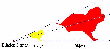
Figure 4.22: Similarity Transformation with r < 1.0